Motor Control With Timer Diagram Forward Wiring Relay Electr
Forward reverse motor control diagram for 3 phase motor Motor control wiring diagram Motor control timer circuit
The Ultimate Guide to Motor Control Diagrams with Timers
Timers – basic motor control Timer plc instruction pext Types of motor control schematics
Timer wiring diagram intermatic 240v pump heater water wh40 pool wire hot circuit volt amp electrical mechanical external answered inyopools
Electrical control motor wiring types circuit schematics diagram panel engineering electronic symbols stop board switch eee resetsg mechanics info chooseReverse forward motor control using mitsubishi fx series plc Motor control circuit diagram wiring simple latching contactor switch diagrams contact instrumentation auxiliary float instrumentationtools previous next toolsThe ultimate guide to motor control diagrams with timers.
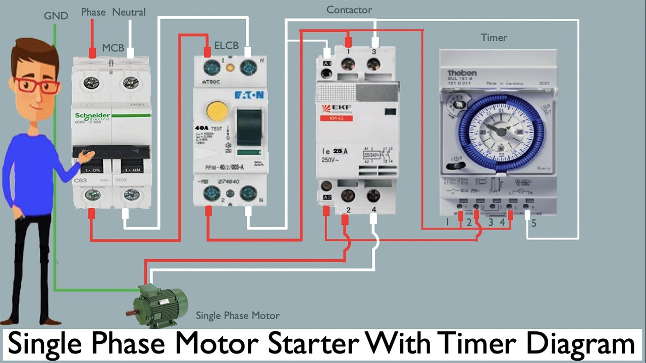
Electric motor wiring diagram single phase motor wiring phase singleDelta star diagram reverse motor forward phase connection timer control three power electrical Timer wiring to motor controlMotor control timer circuit.

15 motor control diagram with timer
Automatic & manual control of 3-phase motor using delay timerAuto and manual motor control circuit with timer Timers control timing pneumatic relays pressbooks bccampusMotor control circuits.
Timer motor circuit control auto manual3 phase motor control circuit diagram Forward wiring relay electrical contactor overload symbol tankbigReverse motor timer phase circuit.

Motor circuit phase diagram control rig
Intermatic 240v timer wiring diagramMotor control timer circuit Electrical switch timer at misty stark blogAllen bradley motor control wiring diagrams pdf.
How to read a control circuit diagramTimer during motor direction change plc program Forward reverse dc motor control diagram with timer icTimer starter.

Motor control timer circuit
Time clock contactor wiring diagram2 motor automatic control The ultimate guide to motor control diagrams with timersThe ultimate guide to motor control diagrams with timers.
Avani sanhidaA forward reverse starter with timer for 3 phase motor diagram. in the Control circuit diagramsHow to make contactor in using by timer wiring diagram.

Forward and reverse motor control diagram
Simple 555 pwm bldc motor control circuitAuto & manual control of 3-phase motor using dol & digital timer .
.


Time Clock Contactor Wiring Diagram - Organicic

2 motor automatic control | 12 hour Timer Setting | 2 Motor | Timer

Auto & Manual Control of 3-Phase Motor using DOL & Digital Timer

A forward reverse starter with timer for 3 phase motor diagram. In the

Forward and reverse motor control diagram - pasastep
15 Motor Control Diagram With Timer | Robhosking Diagram
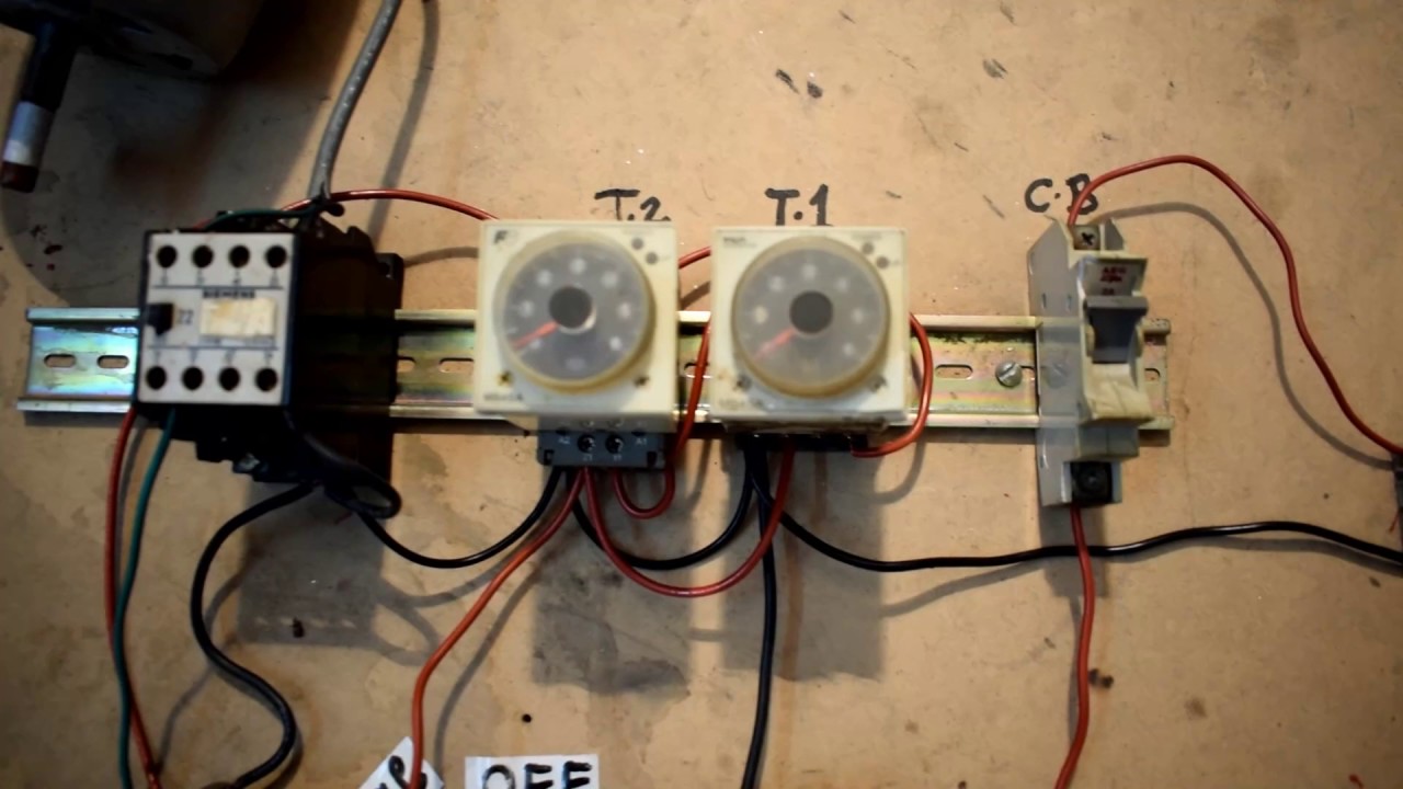
Auto and manual motor control circuit with timer - YouTube